
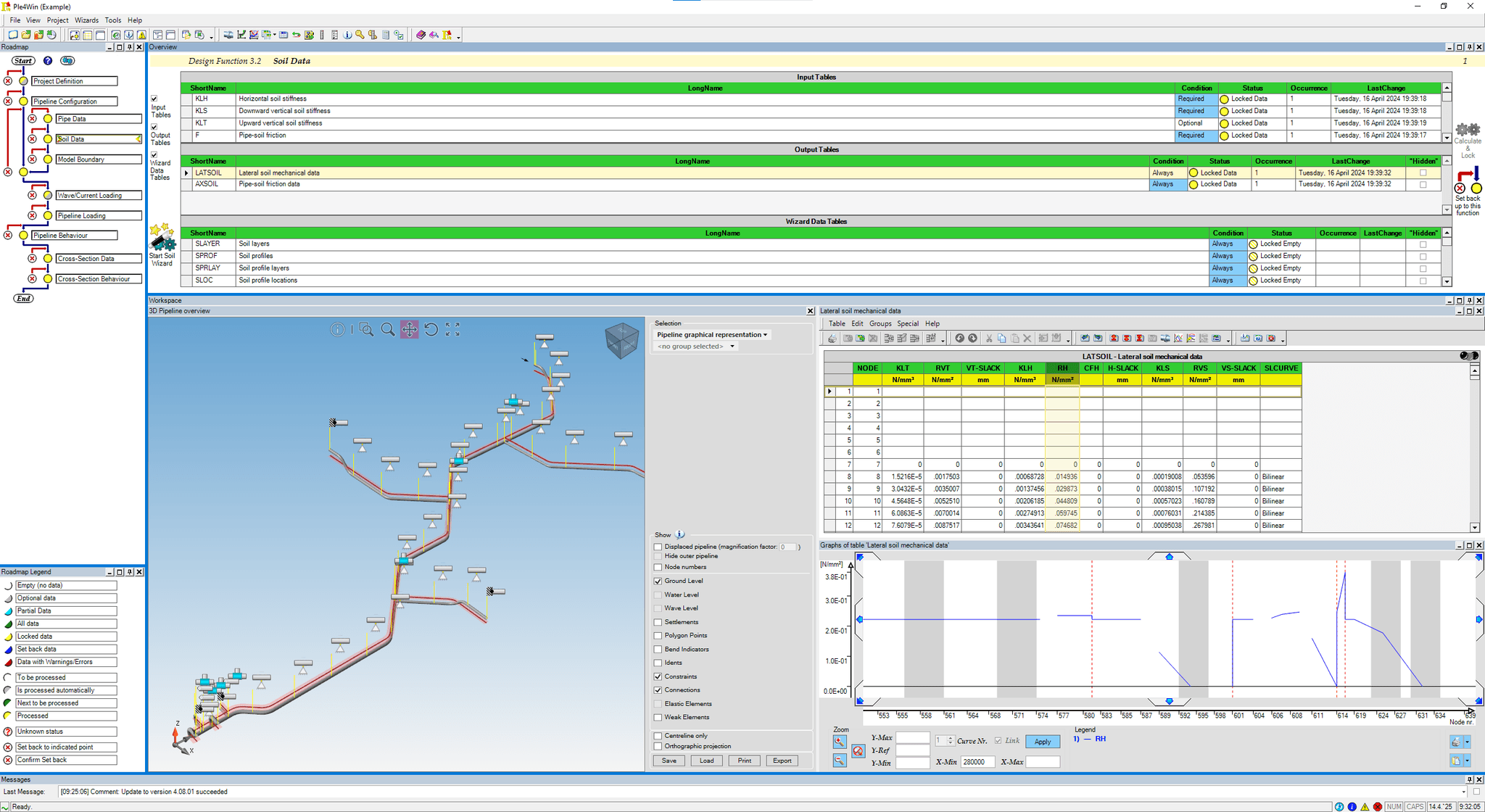
PLE is based on a 3D geometric model, in which the pipeline is schematised by means of a string of straight pipe, (elastically) curved bend, support, joint and T-connection elements.
Branches and loops are allowed and as a result stations may be analysed as well.
Pipe diameter, pipe wall thickness with manufacturing tolerance and corrosion allowance, and the isotropic or anisotropic properties of the pipeline materials may vary along the pipeline axis.
At the locations of the bends (toroids) the reduction of the bending stiffness of the cross section, as a result of ovalisation, is taken into account. The counteracting effect of the internal pressure on this stiffness reduction is considered as well.
Support and loading of the pipeline result from the surrounding soil. The soil model is based on the mechanical properties of the soil, which depend on the deformation direction (upward, sideward and downward) of the pipe relative to the soil and counteracted by the friction reaction of the soil.
Based on soil failure mechanics in the four principal directions a 3-D soil model is built in such a way that in the model the soil reaction is defined in any direction of the pipeline displacement. The deformation behaviour of the soil is considered to be non-linear elastic or elasto-plastic and primarily based on a bi-linear curve. Over the first part of the curve the deformation behaviour of the soil is considered to be linear elastic (constant ratio between soil reaction and pipe displacement), whereas over the second part the soil behaviour is considered to be ideal plastic (constant soil reaction independent of the pipe displacement). Other, smooth, curves can be applied too. Even slacks (for instance in a jacket tube) are possible.
At the pipe bottom, variable soil support angles and at the sides horizontal soil support may be applied.
At the end points of the pipeline structure to be taken into account, a free end or rigid support or a connected half-infinite long pipeline can be specified. Along the pipeline axis external linear elastic supports can be specified. For instance a “table” support with friction properties.
The loadings that may be placed on the pipeline structural model result from:
- Installation conditions (elastic bends, towing forces focused on the pulling point, preheating conditions, sequence of installation phases);
- Operational conditions (internal or external overpressure, variations in temperature, deadweight of the pipeline structure);
- Environmental conditions (3-D deformations of the surrounding soil as a result of consolidation settlements from extra loading and soil subsidence as result of disturbance of the soil structure or earthquakes, overburden soil weight, temporary loadings on top of the soil, e.g. as a result of traffic loads, wave and current loadings at sea, wind, snow and ice loads);
- Additional loadings may be modelled by means of point load patterns.
Multiple analysis methods are available to the user, specifically:
- Allowable stress method (linear elastic (an)isotropic pipe material, soil non-linear behaviour, geometric linear or non-linear behaviour, all loads without design factor, sequential loading allowed) with evaluation on basis of allowable stress level (based on safety factor), allowable deformation and overall buckling;
- Limit stress method (linear elastic (an)isotropic pipe material, soil non-linear behaviour, geometric linear or non-linear behaviour, loads with specific design factors, sequential loading allowed, limited once-only yielding implicitly allowed by application of stress correction factors) with evaluation on basis of ultimate (yield) stress, alternating yielding and overall buckling;
- Limit strain method (elasto-plastic isotropic pipe material, several stress-strain relations, geometric linear or non-linear behaviour, soil non-linear behaviour, loads with specific design factors, sequential loading not allowed) with evaluation on basis of ultimate strain, alternating yielding and local buckling.
The results of analysis are presented in a hybrid fashion:
- Longitudinal (beam) behaviour (pipe displacements, internal forces, soil and external support reactions, stiffness reduction and stress intensification factors for bends and T-connections, axial and rotational displacements in joint elements, free spans both above and below ground level);
- Cross-section behaviour (all cross-sectional loadings, cross-sectional deformations, longitudinal and circumferential stresses and strains, hoop stress, equivalent stress and strain according to Von Mises, principal stress and strain according to Mohr, shear stress and strain according to Tresca, uni-axial stresses and strains);
- Results can be shown in multiple formats (tabular, X-Y graphs, polar graphs, multiple combined graphs, 2D schematics, 3D visualisation of displacements, data as colours over a 3D model of the pipeline).
History Program:
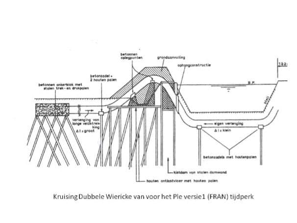
The Ple4Win program has a long history. The beginnings date back to 1965, when the Dutch Gasunie encountered a problem during the construction of the first high-pressure gas pipeline from the north of the Netherlands (Friesland) to the west of the country (the “Randstad”). The pipe had to cross the Dubbele Wiericke, an important dike. The Dutch authority Rijkswaterstaat demanded a “safe” construction of this crossing. As there was no knowledge about pipeline behaviour in soft soils, a very sturdy, complex and expensive crossing was build:

View of the Dubbele Wiericke, not far from the actual pipeline crossing
To construct each crossing of an important dike the same way was neither practical not affordable. Therefore, research into pipe behaviour, pipe-soil interaction and automated stress and strain calculations of buried pipelines was initiated, ultimately leading to the current program. So far, there have been four generations in that series, starting with HADIS/FRAN/STRESS (mainframe), Belipo (mini-computers), PLE-micro-CAD (CP/M and DOS) and currently Ple4Win (Windows).